

Q.1 A) What is Framing explain in sort different framing method
Framing is a function of the data link layer.
It provides a way for a sender to transmit a set of bits that are meaningful to the receiver.
Ethernet, token ring, frame relay, and other data link layer technologies have their own frame structures.
Frames have headers that contain information such as error-checking codes.
Methods of Framing :
There are basically four methods of framing as given below
1. Character Count
2. Flag Byte with Character Stuffing
3. Starting and Ending Flags, with Bit Stuffing
4. Encoding Violations
These are explained as following below.
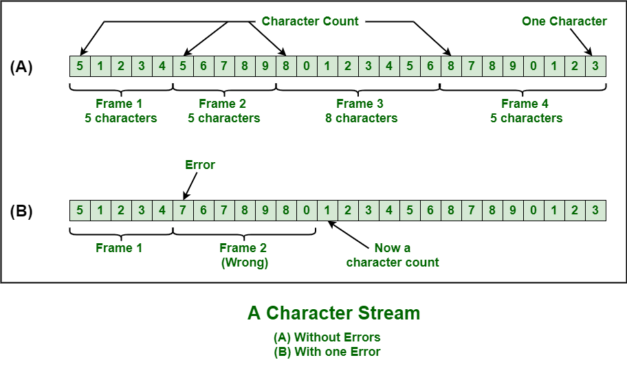
- Character Count :
This method is rarely used and is generally required to count total number of characters that are present in frame. This is be done by using field in header. Character count method ensures data link layer at the receiver or destination about total number of characters that follow, and about where the frame ends.There is disadvantage also of using this method i.e., if anyhow character count is disturbed or distorted by an error occurring during transmission, then destination or receiver might lose synchronization. The destination or receiver might also be not able to locate or identify beginning of next frame.
- Character Stuffing :
Character stuffing is also known as byte stuffing or character-oriented framing and is same as that of bit stuffing but byte stuffing actually operates on bytes whereas bit stuffing operates on bits. In byte stuffing, special byte that is basically known as ESC (Escape Character) that has predefined pattern is generally added to data section of the data stream or frame when there is message or character that has same pattern as that of flag byte.But receiver removes this ESC and keeps data part that causes some problems or issues. In simple words, we can say that character stuffing is addition of 1 additional byte if there is presence of ESC or flag in text.

- Bit Stuffing :
Bit stuffing is also known as bit-oriented framing or bit-oriented approach. In bit stuffing, extra bits are being added by network protocol designers to data streams. It is generally insertion or addition of extra bits into transmission unit or message to be transmitted as simple way to provide and give signaling information and data to receiver and to avoid or ignore appearance of unintended or unnecessary control sequences.It is type of protocol management simply performed to break up bit pattern that results in transmission to go out of synchronization. Bit stuffing is very essential part of transmission process in network and communication protocol. It is also required in USB.
- Physical Layer Coding Violations :
Encoding violation is method that is used only for network in which encoding on physical medium includes some sort of redundancy i.e., use of more than one graphical or visual structure to simply encode or represent one variable of data.
Q.1 B) Discuss design issues of various layer
The following are the design issues for the layers:
Reliability: It is a design issue of making a network that operates correctly even when it is made up of unreliable components.
Addressing: There are multiple processes running on one machine. Every layer needs a mechanism to identify senders and receivers.
Error Control: It is an important issue because physical communication circuits are not perfect. Many error detecting and error correcting codes are available. Both sending and receiving ends must agree to use any one code.
Flow Control: If there is a fast sender at one end sending data to a slow receiver, then there must be flow control mechanism to control the loss of data by slow receivers. There are several mechanisms used for flow control such as increasing buffer size at receivers, slow down the fast sender, and so on. Some process will not be in position to accept arbitrarily long messages. This property leads to mechanisms for disassembling, transmitting and the reassembling messages.
Multiplexing and De-multiplexing: If the data has to be transmitted on transmission media separately, it is inconvenient or expensive to setup separate connection for each pair of communicating processes. So, multiplexing is needed in the physical layer at sender end and de-multiplexing is need at the receiver end.
Scalability: When network gets large, new problem arises. Thus scalability is important so that network can continue to work well when it gets large.
Routing: When there are multiple paths between source and destination, only one route must be chosen. This decision is made on the basis of several routing algorithms, which chooses optimized route to the destination.
Confidentiality and Integrity: Network security is the most important factor. Mechanisms that provide confidentiality defend against threats like eavesdropping. Mechanisms for integrity prevent faulty changes to messages.
Q.1 C )Compare TCP IP and OSI reference model
|
TCP/IP |
OSI |
|
TCP refers to Transmission Control Protocol. |
OSI refers to Open Systems Interconnection. |
|
TCP/IP has 4 layers. |
OSI has 7 layers. |
|
TCP/IP is more reliable |
OSI is less reliable |
|
TCP/IP does not have very strict boundaries. |
OSI has strict boundaries |
|
TCP/IP follow a horizontal approach. |
OSI follows a vertical approach. |
|
TCP/IP uses both session and presentation layer in the application
layer itself. |
OSI uses different session and presentation layers. |
|
TCP/IP developed protocols then model. |
OSI developed model then protocol. |
|
Transport layer in TCP/IP does not provide assurance delivery of
packets. |
In OSI model, transport layer provides assurance delivery of packets. |
|
TCP/IP model network layer only provides connection less services. |
Connection less and connection oriented both services are provided by
network layer in OSI model. |
|
Protocols cannot be replaced easily in TCP/IP model. |
While in OSI model, Protocols are better covered and is easy to
replace with the change in technology. |
Q.1 D ) Various Error reporting messages in internet control Message protocol
(ICMP) is a protocol used for error handling and debugging in the network layer. It is mainly used in network devices such as routers.
ICMP messages are mainly divided into two categories :
- Error reporting messages
- Query messages
Error Reporting Messages are used to report problems encountered by the router/host while processing the IP packets. These messages are always sent to the source because the datagram only contains the source and destination IP address.
Following are the types of error reporting messages :
- Destination Unreachable Message –
The host/router send this message if it is not able to route the IP packet to its destination.
For example, sender A wants to send the datagram to receiver B but it is not received by B then the intermediate router will discard the datagram and send the destination unreachable message to A.
- Source Quench Message –
Host/router send this message if there is congestion in the network or the source is sending packets at a higher rate which the router can’t handle.
For example, if sender A is sending the data packets at a high data rate which the router is unable to handle then it will discard the packet and send a source quench message to A to tell it to send the packets at a lower rate. Now, after receiving the message A will either stop or slow down sending of the packets.
- Time Exceeded Message –
The host/router sends this message if it decrements the time to live value of the datagram to zero or the destination address does not receive all the packets in the specified time interval.
For example, a packet is sent from a layer having 1000 units to the layer having 200 units, then the packet is divided into five fragments. If all the fragments don’t reach the destination in a set time, all fragments are discarded and the time-exceeded message is sent to the original source.
- Parameter Problem Message –
The host/router sends this message if some parameter is not properly set in the datagram. It is used to indicate errors in the header field of the datagram.
- Redirection Message –
The host/router sends this message to update the routing table of the host.
For example, sender A wants to send the message to receiver B and there is a router between them. Then, A sends the data to the router and the router sends the message to B and redirection message to A so that A can update its routing table.
Q.2 A) what is congestion control? Explain various congestion prevention policies.
Congestion:
- Congestion is an important issue that can arise in packet switched network.
- Congestion is a situation in Communication Networks in which too many packets are present in a part of the subnet.
- Congestion in a network may occur when the load on the network is greater than the capacity of the network.
- Due to Congestion the performance degrades.
Factors that Causes the Congestion:
Packet arrival rate exceeds the outgoing link capacity.
Insufficient memory to store arriving packets.
Bursty traffic.
Slow processor.
Congestion Control:
- Congestion Control is the techniques and mechanisms which can either prevent congestion from happening or remove congestion after it has taken place.
- Congestion control mechanisms are divided into two categories, one category prevents the congestion from happening and the other category removes congestion after it has taken place.

I) Open Loop Congestion Control:
In Open Loop Congestion Control, policies are used to prevent the congestion before it happens.
Congestion control is handled either by the source or by the destination.
II) Closed Loop Congestion Control:
Closed loop congestion control mechanisms try to remove the congestion after it happens.
It uses some kind of feedback.
NEED of Congestion Control:
- It is not possible to completely avoid the congestion but it is necessary to control it.
- Congestions leads to a large Queue Length.
- It results in Buffer Overflow & Loss of Packets.
- So the congestion control is necessary to ensure that the user gets the negotiated Quality of Services.
Congestion prevention policies:
I) Retransmission Policy:
The sender retransmits a packet, if it feels that the packet it has sent is lost or corrupted.
However retransmission increases the congestion in the network.
But we need to implement good retransmission policy to prevent congestion.
The retransmission policy and the retransmission timers need to be designed to optimize efficiency and at the same time prevent the congestion.
II) Window Policy:
To implement window policy, selective reject window method is used for congestion control.
Selective Reject method is preferred over Go-back-n window as in Go-back-n method, when timer for a packet times out, several packets are resent, although some may have arrived safely at the receiver.
Thus, this duplication may make congestion worse.
Selective reject method sends only the specific lost or damaged packets.
III) Acknowledgement Policy:
The acknowledgement policy imposed by the receiver may also affect congestion.
If the receiver does not acknowledge every packet it receives it may slow down the sender and help prevent congestion.
Acknowledgments also add to the traffic load on the network.
Thus, by sending fewer acknowledgements we can reduce load on the network.
To implement it, several approaches can be used:
A receiver may send an acknowledgement only if it has a packet to be sent.
A receiver may send an acknowledgement when a timer expires.
A receiver may also decide to acknowledge only N packets at a time.
IV) Discarding Policy:
A router may discard less sensitive packets when congestion is likely to happen.
Such a discarding policy may prevent congestion and at the same time may not harm the integrity of the transmission.
V) Admission Policy:
An admission policy, which is a quality-of-service mechanism, can also prevent congestion in virtual circuit networks.
Switches in a flow, first check the resource requirement of a flow before admitting it to the network.
A router can deny establishing a virtual circuit connection if there is congestion in the network or if there is a possibility of future congestion.
Q.2 B) Explain working of SMTP
SMTP represents Simple Mail Transfer Protocol. SMTP is a set of interaction guidelines that allow the software to transmit electronic mail over the internet, referred to as Simple Mail Transfer Protocol.
The main objective of SMTP is used to set up communication rules between servers. The servers have a way of recognizing themselves and announcing what kind of communication they are trying to perform. They also have a way of handling errors such as incorrect email address.
For example, if the recipient address is wrong, then receiving a server reply with an error message of some kind.
Working of SMTP
SMTP is an end-to-end delivery in which an SMTP client machine contacts the destination host's SMTP server directly to deliver this mail.
Unlike the store and the forward principle that provides the mail content to the destination host through several intermediary nodes in the same network, SMTP continues the mail content being sent until it has been successfully copied to its SMTP.
SMTP maintains only delivery to the mail-gateway host, not to the actual destination host, located beyond the TCP/IP network.
In the mail gateway, the SMTP end-to-end transmission is hosted to the gateway, gateway to host or gateway-to-gateway.
SMTP does not determine the format of mail beyond the gateway.
Each message of the SMTP contains the following field:
- A header or envelop a null line terminates that.
- Contents − Everything after the invalid or blank line is the message body with a sequence of lines containing ASCII characters.
Simple Mail Transfer Protocols represents a client/server protocol. The client SMTP device initiates the session by sending an SMTP message, and the mail server responds by receiving an SMTP message to the session request.
Q.3 A) Explain IPv4 header format in detail. If value at HLEN field is 1101 find the size of option and padding field?
IP Protocol:
- IP Protocol Stands for Internet Protocol.
- It is host to host network layer delivery protocol designed for the internet.
- It is connectionless datagram protocol.
- It is unreliable protocol because it does not provide any error or flow control.

I) Version: This Field defines the version of IP. It is Static 4 bit value.
II) Header Length: This Field defines the length of the datagram header. It is 4 bit value.
III) Type of Service: It is 8 bit value. It is used tell the network how to treat the IP packet. These bits are generally used to indicate the Quality of Service (QoS) for the IP Packet.
IV) Packet Length: 16 bit value indicating the size of the IP Packet in terms of bytes. This gives a maximum packet size of 65536 bytes.
V) Identification: 16 bit field used for reassembling the packet at the destination.
VI) Flags: It is 3 bits value. It indicates if the IP packet can be further fragmented or not and if the packet is the last fragment or not of a larger transfer.
VII) Fragment offset: 13 bit value used in the reassembly process at the destination.
VIII) Time to Live: 8 bit value telling the network how long an IP packet can exist in a network before it is destroyed.
IX) Protocol: 8 bit value used to indicate the type of protocol being used (TCP, UDP etc.).
X) Header checksum: It is 16 bit value. It is used to indicate errors in the header only. Every node in the network has to check and re-insert a new checksum as the header changes at every node.
XI) Source address: 32 bit value representing the IP address of the sender of the IP packet.
XII) Destination address: 32 bit value representing the IP address of the packets final destination.
XIII) Options: Options are not required for every datagram. They are used for network testing and debugging.
XIV) Padding: Variable size bit field. These bits are used to ensure a 32 bit boundary for the header is achieved.
Example:
If value at HLEN field is 1101 find the size of option and padding field.
HLEN Value = 1101 = 13 Bytes.
Total No. of Bytes in the Header = 13 x 4 = 52 Bytes.
The first 20 bytes are the main header and the next 32 bytes are the options + Padding Field.
Q.3 B)Explain CSMA protocol and how are Collison handled in CSMA/CD?
CSMA Protocols stands for Carrier Sense Multiple Access Protocols. CSMA is a network access method used on shared network topologies such as Ethernet to control access to the network. Devices attached to the network cable listen (carrier sense) before transmitting. If the channel is in use, devices wait before transmitting. MA (Multiple Access) indicates that many devices can connect to and share the same network. All devices have equal access to use the network when it is clear.
Types of CSMA Protocols:
1.Persistent CSMA
In this method, station that wants to transmit data continuously senses the channel to check whether the channel is idle or busy.
If the channel is busy, the station waits until it becomes idle.
When the station detects an idle-channel, it immediately transmits the frame with probability 1. Hence it is called I-persistent CSMA.
This method has the highest chance of collision because two or more stations may find channel to be idle at the same time and transmit their frames.
When the collision occurs, the stations wait a random amount of time and start all over again.
Advantages:
- Due to carrier sense property 1-persistent CSMA gives better performance than the ALOHA systems.
Disadvantages:
- Propagation Delay
2.Non-Persistent CSMA
In this scheme, if a station wants to transmit a frame and it finds that the channel is busy (some other station is transmitting) then it will wait for fixed interval of time.
After this time, it again checks the status of the channel and if the channel is free it will transmit.
A station that has a frame to send senses the channel.
If the channel is idle, it sends immediately.
If the channel is busy, it waits a random amount of time and then senses the channel again.
In non-persistent CSMA the station does not continuously sense the channel for the purpose of capturing it when it detects the end of previous transmission.
Advantages:
- It reduces the chance of collision and leads to better channel utilization,
Disadvantages:
- It reduces the efficiency of network because the channel remains idle and it leads to longer delays than 1-persistent CSMA.
3.P-Persistent CSMA
Used for slotted channels.
When a station becomes ready to send, it senses the channel.
In this method after the station finds the line idle, it may or may not send.
If a station senses an idle channel it transmits with a probability p and refrains from sending by probability (1-p).
4.CSMA/CD
Ethernet (IEEE 802.3) sends data using CSMA/CD (CSMA with Collision Detection). CSMA was an improvement over ALOHA as the channel was sensed before transmission begins. Now a further improvised CSMA, in the form of CSMA/CD has been brought about. In this stations abort their transmission as soon as they detect a collision.
Working:
- If two stations sense the channel to be idle they begin transmitting simultaneously and cause a collision.
-A collision is indicated by a high voltage.
Both the stations monitor the channel for a collision and stop transmitting as soon as a collision is detected.
Now the stations wait for a random amount of time and check if channel is free.
The proces
s continues.
How long will it take a station to realize that a collision has taken place?
Let the time for a signal to propagate between the two farthest stations be
Q.4 A) Explain working of link State Routing algorithm explain content and requirement of link state packets
Link-state routing protocols are one of the two main classes of routing protocols used in packet switching networks for computer communications, the other being distance-vector routing protocols. Examples of link-state routing protocols include Open Shortest Path First (OSPF) and intermediate system to intermediate system (IS-IS).
The link-state protocol is performed by every switching node in the network (i.e., nodes that are prepared to forward packets; in the Internet, these are called routers). The basic concept of link-state routing is that every node constructs a map of the connectivity to the network, in the form of a graph, showing which nodes are connected to which other nodes. Each node then independently calculates the next best logical path from it to every possible destination in the network. The collection of best paths will then form the node's routing table.
With link-state routing protocols, a link is an interface on a router. Information about the state of those links is known as link-states.
All routers in an OSPF area will complete the following generic link-state routing process to reach a state of convergence:
- Each router learns about its own links and its own directly connected networks. This is done by detecting that an interface is in the up state.
- Each router is responsible for meeting its neighbors on directly connected networks. Link-state routers do this by exchanging Hello packets with other link-state routers on directly connected networks.
- Each router builds a link-state packet (LSP) containing the state of each directly connected link. This is done by recording all the pertinent information about each neighbor, including neighbor ID, link type, and bandwidth.
- Each router floods the LSP to all neighbors. Those neighbors store all LSPs received in a database. They then flood the LSPs to their neighbors until all routers in the area have received the LSPs. Each router stores a copy of each LSP received from its neighbors in a local database.
- Each router uses the database to construct a complete map of the topology and computes the best path to each destination network. Like having a road map, the router now has a complete map of all destinations in the topology and the routes to reach them. The SPF algorithm is used to construct the map of the topology and to determine the best path to each network.
Dijkstra’s Algorithm
All link-state routing protocols apply Dijkstra’s algorithm to calculate the best path route. The algorithm is commonly referred to as the shortest path first (SPF) algorithm. This algorithm uses accumulated costs along each path, from source to destination, to determine the total cost of a route.
In figure below, each path is labeled with an arbitrary value for cost.

Q.4 B) Explain congestion control approaches in TCP
TCP Congestion Policy-
TCP’s general policy for handling congestion consists of following three phases-

- Slow Start
- Congestion Avoidance
- Congestion Detection
1. Slow Start Phase-
- Initially, sender sets congestion window size = Maximum Segment Size (1 MSS).
- After receiving each acknowledgment, sender increases the congestion window size by 1 MSS.
- In this phase, the size of congestion window increases exponentially.
The followed formula is-
| Congestion window size = Congestion window size + Maximum segment size |
2. Congestion Avoidance Phase-
After reaching the threshold,
- Sender increases the congestion window size linearly to avoid the congestion.
- On receiving each acknowledgement, sender increments the congestion window size by 1.
The followed formula is-
| Congestion window size = Congestion window size + 1 |
This phase continues until the congestion window size becomes equal to the receiver window size.
3. Congestion Detection Phase-
When sender detects the loss of segments, it reacts in different ways depending on how the loss is detected-
Case-01: Detection On Time Out-
- Time Out Timer expires before receiving the acknowledgement for a segment.
- This case suggests the stronger possibility of congestion in the network.
- There are chances that a segment has been dropped in the network.
Reaction-
In this case, sender reacts by-
- Setting the slow start threshold to half of the current congestion window size.
- Decreasing the congestion window size to 1 MSS.
- Resuming the slow start phase.
Case-02: Detection On Receiving 3 Duplicate Acknowledgements-
- Sender receives 3 duplicate acknowledgements for a segment.
- This case suggests the weaker possibility of congestion in the network.
- There are chances that a segment has been dropped but few segments sent later may have reached.
Q.5 A)Explain file transfer protocol
File Transfer Protocol (FTP) is the standard mechanism provided by TCP/IP for copying a file from one host to another.
• Although transferring files from one system to another seems simple and straightforward, some problems must be dealt with first.
• For example, two systems may use different file name conventions. Two systems may have different ways to represent text and data.
• Two systems may have different directory structures. All these problems have been solved by FTP in a very simple and elegant approach.
• FTP differs from other client/server applications in that it establishes two connections between the hosts. One connection is used for data transfer, the other for control information (commands and responses).
• Separation of commands and data transfer makes FTP more efficient. The control connection uses very simple rules of communication.
• Wc need to transfer only a line of command or a line of response at a time. The data connection, on the other hand, needs more complex rules due to the variety of data types transferred. However, the difference in complexity is at the FTP level, not TCP.
• For TCP, both connections are treated the same. FTP uses two well-known TCP ports: Port 21 is used for the control connection, and port 20 is used for the data connection.
FTP uses the services of TCP. It needs two TCP connections. The well-known port 21 is used for the control connection and the well-known port 20 for the data connection
• Figure shows the basic model of FTP.
• The client has three components: user interface, client control process, and the client data transfer process.
• The server has two components: the server control process and the server data transfer process.
• The control connection is made between the control processes. The data connection is made between the data transfer processes.

• The control connection remains connected during the entire interactive FTP session.
• The data connection is opened and then closed for each file transferred. It opens each time commands that involve transferring files are used, and it closes when the file is transferred.
In other words, when a user starts an FTP session, the control connection opens. While the control connection is open, the data connection can be opened and closed multiple times if several files are transferred.
Q.5 B)Explain sliding window protocol using go back n technique
Frames are transmitted in both directions.
It requires a full duplex communication channel.
i. It uses Piggy Backing which means that the outgoing acknowledgement is delayed so that they can be hooked to the next outgoing data frame.
ii. Piggy backing is used so that there is no need to send a separate acknowledgement frame; thus saving bandwidth.
iii. In piggy backing we have to only set/reset the ack field which consists of a few bits. If a separate acknowledgement frame had to be sent it would need a header and a checksum, thus using more bits.
Sending Window: Represents the frame numbers that have been sent but are yet not acknowledged.
Receiving Window: Represents the frame numbers that the receiver can accept.
GO BACK N Protocol
In this case when a damaged frame arrives the receiver simply discards all the subsequent frames.
It can transfer more than one frame at a time thus it is faster than the 1-bit sliding window protocol.
Working: Sender sends N frames and waits for an acknowledgement, if Rth frame is in error, packets received after Rth frame will be discarded and it starts resending from Rth to Nth frame. E.g.: Assume window size= 4 frames.
Suppose sender sends frames 1 to 3.
It has to now wait for the acknowledgement before it can proceed.
As each successive acknowledgement is received the window slides forward and the sender can send the next frames.
Suppose an acknowledgement of the 0 frame is lost then the sender discards all the frames after the lost frame (i.e. 1, 2, 3) and retransmits from the 0th frame.
Max Senders Window Size = 2k – 1
Reason:
a. Suppose that we keep window size = 2k
b. Assume k=3, therefore 2k =8
c. At time t1 sends frames 0 to 7 to /b.
d. B receives each of them in order and at time t2 sends acknowledgement for the most recent frame i.e. frame 7.
e. Suppose that this acknowledgement gets lost.
f. Now B does not know that the acknowledgement it send is lost.
g. A does not receive the acknowledgement and times out. On timing out it resends the frames 0 to 7 to B.
h. But it is a duplicate of the frames that were already received by B.
i. This problem occurs because 2 consecutive windows contain the same frame numbers. Reducing the frame size by 1 solves this problem.
j. Hence maximum sender window size 2k – 1.
Max Receivers Window size =1.
Reason: The frames are always received in order
The frames must be received in order.
Simple Network Management Protocol (SNMP) is an application-layer protocol used to manage and monitor network devices and their functions. SNMP provides a common language for network devices to relay management information within single- and multivendor environments in a local area network (LAN) or wide area network (WAN). The most recent iteration of SNMP, version 3, includes security enhancements that authenticate and encrypt SNMP messages as well as protect packets during transit.

Components of SNMP
There are four main components in an SNMP-managed network:
SNMP agent: This program runs on the hardware or service being monitored, collecting data about various metrics like bandwidth use or disk space. When queried by the SNMP manager, the agent sends this information back to the management system. An agent may also proactively notify the NMS if an error occurs. Most devices come with an SNMP agent preinstalled; it typically just needs to be turned on and configured.
SNMP-managed devices and resources: These are the nodes on which an agent runs.
SNMP manager (aka NMS): This software platform functions as a centralized console to which agents feed information. It will actively request agents send updates via SNMP at regular intervals. What a network manager can do with that information depends heavily on how feature-rich the NMS is. There are several free SNMP managers available, but they are typically limited in their capabilities or the number of nodes they can support. At the other end of the spectrum, enterprise-grade platforms offer advanced features for more complex networks, with some products supporting up to tens of thousands of nodes.
Management information base (MIB): This database is a text file (.mib) that itemizes and describes all objects used by a particular device that can be queried or controlled using SNMP. This database must be loaded into the NMS so that it can identify and monitor the status of these properties. Each MIB item is assigned an object identifier (OID).
- ARP stands for Address Resolution Protocol.
- It is the protocol used by Internet Protocol (IP) specifically IPv4.
- This protocol operates below the network layer as a part of the interface between the OSI network and OSI link layer.
- It is used to map Logical Addresses to the Physical Addresses used by a data link protocol.
- ARP Simply Converts IP Address to Physical Address.
- It is relatively simple Request-and-Reply Protocol.
ARP Request & Reply:

ARP maintains the mapping between IP address and MAC address in a table in memory called ARP cache.
The entries in this table are dynamically added and removed.
A host will update its ARP cache, only if the ARP request is for its IP address.
Otherwise, it will discard the ARP request.
Consider the above figure, in this a Host sends out the Request Message.
It is looking for the MAC Address of the node with IP Address 192.168.1.220.
The Node with the IP Address 192.168.1.220 sends out the Reply Message.
In reply message it sends its MAC Address to the Host.
- It is a wireless technology therefore susceptible to spying and remote access.
- Bluetooth offers several security modes.
- Bluetooth users can establish "Trusted devices"that can exchange data without asking permission.
- When any other device tries to establish a connection to the users gadget,the user has to decide to allow it.
- "Service level security" and "Device level security" work together to protect Bluetooth devices from unauthorized data transmission.
- Security methods includes authorization and identification procedures that limit the use of Bluetooth services to the registered user and require that users make a conscious decision to open a file or accept data transfer.
Services can have one of 3 security levels:-
Level 1: Open to all devices,the default level.
Level 2: Authentication only,fixed PIN
Level 3: Requires authentication and authorization PIN number must be entered
Link level security:
This is implemented bye symmetric keys in a challenge response system.
Critical Ingredients: PIN, BD_ADDR, RAND(), Link and encryption keys.
PIN: It is up to 128bit number,can be fixed.Can be entered in both the devices.
BD_ADDR: Bluetooth device address-It is unique 48 bit sequence.Device must know the address for communication.
Link key: 128 bit random number is used for authentication purposes.Paired devices share a link key.
Private encryption key: 8-128 bits key regenerated for transmission from link key.
RAND: Frequently changing 128 bit,Random number generated by the device.
Q.6 D) Short note on Barclay Socket
Socket:
- Sockets are a service provided by transport layer.
- A socket is one endpoint of a two-way communication link between two programs running on the network.
Berkeley Socket:
- Berkeley sockets is an application programming interface (API) for Internet sockets and UNIX domain sockets.
- It is used for inter-process communication (IPC).
- It is commonly implemented as a library of linkable modules.
- It originated with the 4.2BSD UNIX released in 1983.
Primitive used in Berkeley Socket:

Socket Programming:
I) Server side:
Server startup executes SOCKET, BIND & LISTEN primitives.
LISTEN primitive allocate queue for multiple simultaneous clients.
Then it use ACCEPT to suspend server until request.
When client request arrives: ACCEPT returns.
Start new socket (thread or process) with same properties as original, this handles the request, server goes on waiting on original socket.
If new request arrives while spawning thread for this one, it is queued.
If queue full it is refused.
II) Client side:
It uses SOCKET primitives to create.
Then use CONNECT to initiate connection process.
When this returns the socket is open.
Both sides can now SEND, RECEIVE.
Connection not released until both sides do CLOSE.
Typically client does it, server acknowledges.


0 Comments